Showing posts with label Dick Kerr WDLR. Show all posts

Tuesday, July 5, 2016

Dick Kerr 12

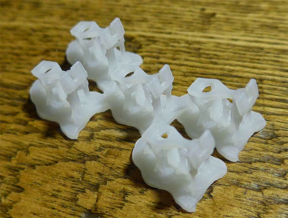
I've been slow in updating the blog, but the Dick Kerr Project is really moving.  There is increasing interest in the possibility of a Dick Kerr kit as people see the project in social media.  I've found that it's possible to achieve the extremely fine detail I want using the Form 2 printer.  This includes profiles beyond the published capabilities of the machine, providing things are appropriately oriented and optimized.  Very glad I upgraded.  A gallery of updates follows.  I'm looking forward to getting this painted.  The floor is laser etched from wood--the only part not made on the Form 2 at this point aside from a couple bits of brass.


Backhead and gears fresh from the printer, Dick Kerr 11

The back head printed beautifully.  The control lever is a bit too far to the left.  I did this for support, but think I can now push it over.  Will also add rivet detail I think.


The chassis looks a bit abstract, but everything seems to fit right.  Looking forward to getting it off the supports.


Gears mesh well! I'm thinking this might actually work now.


Monday, July 4, 2016

Backhead and under the hood for the Dick Kerr 10

I've been busy on the Dick Kerr, mainly working on the "backhead" and technical items.  The detail in the above image looks crude, until you consider how small this little loco is, the cab could be mistaken for an HO scale RS3, and the interior here shown is just a fraction of that.  I've made a couple compromises, but, they should not be noticable through the cab door.


I've also designed a set of spur gears for the revised Mechanism.  The real work was done using the fantastic program Gearotic Motion.  I was originally planning to machine these with the Roland mill, but I am going to use these to put the Form 2 to the test today.  Any significant distortion will cause problems with these small gear of 9mm and 14mm diameter.  If they don't work I can always make them on the Roland.  If they do work, I may need to cast them in a softer plastic.  We'll see.

Bruce Wilson proposed a set up from Hollywood Foundry that looks very good--I may go ahead and make one of my mechanisms, and order a Hollywood Foundry item for the second, just to make the body adaptable to something that is not as custom as my solution.

Friday, June 3, 2016

Dick Kerr 09

A retro-post from June 3, 2016, we're almost caught up.

I've gone ahead and assembled the first set of Dick Kerr Prints.  All I can say is "wow" to the Form 2. Once primed, these will require very little post production.  I'm confident that I can make the body consistently.  Time now to step back and fill in a couple details such as the cab interior and the brake system.  Also need to work out the mechanism mounting.  Briefly flirted with the idea of making this little monster "dead rail" using my new Blue Rail Board from David Rees.


Thursday, June 2, 2016

Another retro-post to catch us up.

The Dick Kerr Coupler printed on Form 2.  The part is designed to fit a standard Kadee draft gear box.  I've added a vertical hole to the pin slot to allow cars to be coupled using a "staple" as a link.  I still need to test whether this can be done with a magnet, but I'll need to get some rolling stock going to do so.


Tuesday, May 31, 2016

Reviving Dick Kerr 08

A retro post from late Spring 2016..... I promise, we're catching up.


The Dick Kerr Project reached a stopping point when we relocated.  To be honest, however, I was at a frustrating juncture because I had designed the pieces based on what I thought were the limits of the Formlabs Form 1.  As it turns out, the parts I designed were right at the limits, and probably slightly beyond judging by the success rate and the gymnastics I had to do to print them consistently.

Enter Form 2.  Thanks to a loyalty upgrade, I switched Form 1 for Form 2.  Before I reworked any files I went ahead and set up prints with the existing file.  All I can say is that the improvements to the peel mechanism, resin level management and laser power make a difference.  Taken together with the addition of a tank heater, the machine is a dream.  Resolution is much more consistent.

Thursday, March 13, 2014

Dick Kerr WDLR 07

Everyone is probably getting bored of the Dick Kerr right now, but it's moving along.  Work has kept me away this week, but I still managed to finish up the cab.  I'm so happy with it that I'm going to take another crack at the sides--I think I can do better.  The test print of the cab is in the printer now.


One thing of note is that I "relieved" the windows in the cab, meaning I tapered the section of the wall near the window so they look near scale thickness.  This allows a thicker body wall. I'm going to give that treatment to the body sides.  You can see the tapering around the windows and the holes in the transparent version below.  I'm waiting to see the test print before I decide how to break it apart.


The other major step forward was developing a WDLR coupler.  I've designed it to work in a Kadee draft gear box.  I'm making a custom Kadee style box for the Kerr.  This way I can use standard Kadee centering springs, and allows for Kadee/WDLR couplers to be interchangeable.


My WDLR coupler head is faithful, save for an additional vertical hole I've added to allow for coupling with a small staple.  It's based on drawings and photos.  Here is the first test print.


Note the heel of the coupler is extended in this version--I had momentarily thought of an alternate centering scenario for use on a WDLR bogie, but quickly realized that the Kadee spring solution was a good one.

Monday, February 24, 2014

Dick Kerr WDLR 06

I've pulled the latest round of prints from the 3d printer, and am really pleased with the results.  I might adjust the assembly but I'm really pleased with the detail.  I'm going to add some relief to a couple edges to make things look thinner, and break the insulators away from the radiator.  The last revisions went really well.


Although I'm excited to work on the cab, I realized that I needed to sort the mechanism.  Returning to my previous work, I started by drawing the gearbox, wheels, and motor in both 2d and 3d.  I dropped the motor and gearbox in the model, and experimented with it's position.  I may abandon the flywheel, as it stands it looks like I can get everything into the hood.  Very cool.


One thing that's been bothering me about my previous work was that I only powered one axle.  Although this might work, with such a small loco and such a small motor I wanted more power transmitted to the rail.  This means connecting things with gears.  There's just enough room in the body cavity to offset the motor to one side and connect the two axles with a series of gears.  I started by drawing the Northwest Short Line spur gear because I thought that I might create a system that was integrated with the NWSL gearbox. . . then better sense prevailed.  A big part of the value of the NWSL gearbox is that the worm and associated thrusts are well worked out: messing with this seemed to invite gremlins.  I can always play with an integrated system later.  


The NWSL gears are all metric, the particular gearbox I chose is .03 MOD.  It seemed logical enough to continue with that gear specification.  I should point out that my version of the NWSL gear is close, but I may not be spot on, because I don't know exactly what the pitch of the NWSL gear is.  I made some good assumptions and may have it, but won't know until I test.  Given that my gears will not interact with the NWSL gears it does not matter, however I'd like to know. . . . 


I've been using Gearotic Motion and AutoCad for my mechanism design.  Gearotic will give you the proper axle spacing between two spur gears.  Using that information, it's possible to layout the precise geometry in AutoCad.  As my plan is to cast the chassis in lead shot filled resin, I'm simply including a minor shrinkage factor in the tolerance.


Gearotic allows you to work from the gear specification and the number of teeth to create a .dxf, stl, or gcode.  Although you can make a printable file from Gearotic, I'll probably use Rhino to design molds.  From there I can make rubber molds and cast gears in engineering resin.  Gearotic Motion was developed by Art Fenerty, who also developed Mach3, a corner stone of the Home CNC comunity.  I love the program.


Sunday, February 23, 2014

Dick Kerr WDLR 05

I traced this page through a stray photo.  It's been extremely helpful to see the radiator more clearly, and to gain some insight on the David Smith Drawings.  Also a clear idea of the hood radiator relationship.  Also note this Dick Kerr does not seem to have the trademark spokes in the front wheel set.  They must have been changed out at some point.  Similarly curious about the exhaust--assuming that's also been revised.

From: http://railsvagabonds.canalblog.com/archives/2012/09/13/25098989.html
No sooner did I find this than Bruce Wilson turned me on to this page.  That's where this fantastic high angle photo resides:

From: http://www.tacot-des-lacs.com/
Seeing this caused me to reconsider how I was joining the hood to the body, and whether I wanted to model the rail along the hood as part of my casting.  It seems to me that I should lower the joint to fit this image better.  Bruce also found this image (attribution in caption):

http://www.16mm.org.uk/newsite/Christmas_Quiz/2012images/Loco10.jpg
This of course clarifies some of the assumptions I have made.  Radiator needs to be deeper, and the insulator bases are indeed massive castings.  The image below illustrates how I've adjusted the rivets on top of the hood to better fit the images here.  While I can't measure them directly, I can adjust the number and spacing.  I now better understand the position of the straps on the roof--those are steel joints that don't necessarily align with the internal framework which is more closely aligned with the doors.  The framework is reflected in the additional lines of rivets.  I've also simplified thicknesses, and accepted 1.5mm as the necessary structural thickness at the sides (where they are not visible).  I've also increased the seam carve away to .4mm.


After tackling the hood, I returned to thickening and revising the insulator and radiator based on the photos.  The text on the radiator was bigger than I thought based on the David Smith drawings, and I chose to exaggerate it a bit more, hoping to make it legible in 7mm scale (1:43.5).  I also removed the "rails", figuring those could be added later with brass if I chose to do so.  I imagine a lot of these items (radiator cover, details) were removed by soldiers.  While it's possible that these parts were not removed until the units were resold as surplus after the war, soldiers are notoriously practical, and hate to waste time.


Here's the revised hood and radiator assembly.  It's off to the printer now.  I am looking forward to spending time on the cab tonight, after some time away from the computer. Getting exciting--I'm hearing the engine in my imagination. . . . .


Wednesday, February 19, 2014

Dick Kerr WDLR 04, Form 1 02

The Dick Kerr project is really moving along.  I've been printing prototypes on the Form 1 and modelling.  In the future I expect things to go faster, however I've been experimenting and learning.

One of the peculiarities of designing things digitally you can draw detail at scale.  Even if you can print it, which the Form 1 can, you can't always see it.  I've spent several hours "beefing up" hardware so it's more visible in the final print.  It looks silly in the 3d model, but boy does it look good output at scale.  The images below illustrate, the lavender color is the exaggerated hardware, the orange is drawn near scale, with some thickness boost to meet minimum resolution requirements.


I've spent a good amount of time in both Rhino and Photoshop, extrapolating, doing and re-doing.  I started with the most delicate parts, and have gradually worked towards the more general ones--all the while re-building parts as needed based on lessons learned from successful and failed prints.


 My build style is to have a mother model based on an AutoCad drawing.  I keep things in logical subassemblies on layers.  I then "move them off" and regroup them as needed to export my .stl files.  This method preserves sanity and maximum flexibility.  I keep the coordinate locations the same between the two softwares, so if I need to work in line I can draw in AutoCad, which is much faster, and then import and know things will line up.  Precision counts.  If in doubt, rebuild it, it's faster than fussing with a repair.


As I make prints I'm updating the model.  Ultimately I'll make the cab to final standard--and skip doing the rivets in true scale, as it's pretty pointless.  


I'm also fairly certain that my ultimate plan will be to cast most of the model in resin, reducing the number of 3d printed parts in the final model.  That way I'll only have to print masters.  As I want a few, and I know Bruce Wilson wants a couple, casting will be more cost effective . . . .especially if I decide to make a few more.  

I have other exciting news on the mechanism design, but I'll save that for when I have some photos.

Thursday, January 31, 2013

Dick Kerr 03

As busy as things are around the farm and work this week, I have still managed a few minutes to choose parts from Northwest Shortline.

I have to admit that I was a bit overwhelmed at first; the online catalog clarified all of my confusion.  The catalog not only gives the dimensions of the various gear boxes, it explains the ins and outs of selecting gear sizes, and gearbox styles.  It is an essential companion to the online store.   [One note, if you land in the online store and press "home", you get to the store home page.  The catalog with the reference material is on the NWSL.com page.  The catalog is the essential reference.]

With this information I was able to make decisions and diagram my drive system:


My first draft included a flywheel.  If I were to continue with this design I would tilt the gearbox so as to have a straight drive-line.  Given my inexperience, I contacted NWSL and e-mailed them the above drawing.  After receiving some advice from them, I decided to drop the flywheel, and straighten the drive out.  I like the straight drive-line better, and it gives me more room for weight.  It will also make my fabrication job a lot easier, as everything will be 90 degrees.

Everyone is very busy in today's world, so extra thanks to David Rygmyr at Northwest Shortline for the advice.  Order placed x 2, as I am building two locos. . .

I should also take a minute to thank the folks at Slater's Plastikard for their help as well.  David Smith, who did the drawings of the locomotive that I am working from, was very helpful regarding the wheels.  I've put links to Slater's Plastikard and NWSL in the links section on the side of this page.  Good people, good companies: a big part of what makes this hobby so enjoyable.

Sunday, January 27, 2013

Dick Kerr 02


Managed a little more progress on the little locomotive. . . mainly because I knocked it on the floor while doing some painting on the Virgin Church (hopefully will update that middle of this week).  After surviving the drop, I figured I owed the superstructure some paper sides.  They fit well, however, they revealed that I had the nose slightly out of square in the "up and down" aspect.  I'll have to add a gusset.


After gluing the sides on, I hit it with some surplus paint (not olive), to see it "as one".  I'm pretty pleased, and I'm excited about the next itteration.  I am thinking that I either need to print paper sides, and paint the superstructure to match, or make the sides out of brass.  The paper does not take to riveting well.  Moreover, there are enough closely spaced rivets in unique patterns that neither decals nor the NWSL riveter will really do it.  I think that manually pricking the rivets in brass using a paper pattern may be the way to go.

All in all, a good stack of work.  I am going to get the mechanism designed before cutting another version. . . .writing to NWSL tomorrow, and looking forward to getting the first wheels in the mail.  Once I get the nuts and bolts worked out, I will start perfecting my skins, and turn my attention to the radiator.


Dick Kerr 01

I've always wanted to build a model of a Dick Kerr Petrol electric locomotive.  While I don't necessarily need another project at the moment, I found myself waiting for bits of this and that on all the other open projects (be it paint drying, or parts in the mail).  So, I got off the sidelines and got going.  Working this project along with the passenger car roof also made the most of every batch of body filler I mixed up.

The latest version of the guts, ultimately to be skinned in brass or paper.
I started the project by building a sketch model in paper.  I am not accustomed to 7mm scale / O-14, so I wanted to see how big this little bugger would be.  In making the sketch model, I did not pay much attention to quality. I just got something together so that I could understand the level of detail necessary in the scale, and so that I could start to imagine how I would navigate the design of the model.  Ultimately, I think I will skin an acrylic substructure with brass or paper, the third version of the substructure has real promise (see the photo above).  The video below describes all the goings on so far, and gives a glimpse of each iteration:


This will be one of the locomotives I intend to use for my "Motive Power" certificate from the NMRA achievement program.  I'm hoping that by documenting the engineering process and thought that goes into the design of the scratch build that folks will not look on my use of the laser cutter with disfavor.   I think the level of drawing and engineering that one does when working with technology is a skill in itself, and deserves as much respect as using a file or piece of sand paper.