Showing posts with label On30. Show all posts

Saturday, July 26, 2025

Current State of the Lost Shore Lines

It's been a while, mainly because I have stopped posting on social media and the internet in general. I just got tired of always taking photos, and I found it slowed me down. These photos show the two portable modules I've been working on, they are 22"x60" and represent the terminus of my Virgin and Lost Shore Railroad at Lost Shore. This entirely fictional railroad is set in 1919 on the coast somewhere between Rhode Island and Maine. It incorporates a lot of my past O Scale structures, and will include the water tower. Here are a couple of overview shots. There is a passing siding, a platform, and a couple of spurs.


The photos above show the first section of water after oil painting. I'm giving it a good long time to cure before doing work with gloss medium and gel medium on top. The following sections show more of an overview to get a sense of where things are.

The basic operating scheme is that trains arrive from a cassette (movable staging) and drop passengers and switch out freight before departing. I've set things up so that cassettes can be double ended. This way the departing train can be used as an arriving train easily.

This represents about half a year of progress. Wiring and track is largely complete, but things have slowed down as I create the paving and other ground work. I need to do some painting....everywhere, and it all seem connected, so I'm working accross both modules and gradually getting it up to snuff.
The harbor bottom and platform are removable, and do a lot to cover the joint between modules. This will also let me change out the harbor, having a ship in port or not, for instance, by swapping out the insert. It slides in a track under the "stone" wall. The platform hides the main wiring junction. Each module has a series of PC ties that all feeders are tied to, there are modular plugs between modules. The modules are sized so I can fit them both in our car with one back seat up, this way If I take them somewhere my son or daughter can come with me.

Tuesday, July 5, 2016

Dick Kerr 12

I've been slow in updating the blog, but the Dick Kerr Project is really moving.  There is increasing interest in the possibility of a Dick Kerr kit as people see the project in social media.  I've found that it's possible to achieve the extremely fine detail I want using the Form 2 printer.  This includes profiles beyond the published capabilities of the machine, providing things are appropriately oriented and optimized.  Very glad I upgraded.  A gallery of updates follows.  I'm looking forward to getting this painted.  The floor is laser etched from wood--the only part not made on the Form 2 at this point aside from a couple bits of brass.


Backhead and gears fresh from the printer, Dick Kerr 11

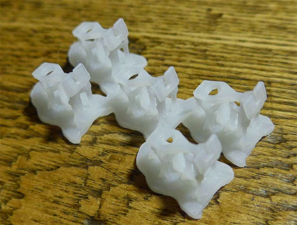
The back head printed beautifully.  The control lever is a bit too far to the left.  I did this for support, but think I can now push it over.  Will also add rivet detail I think.


The chassis looks a bit abstract, but everything seems to fit right.  Looking forward to getting it off the supports.


Gears mesh well! I'm thinking this might actually work now.


Monday, July 4, 2016

Backhead and under the hood for the Dick Kerr 10

I've been busy on the Dick Kerr, mainly working on the "backhead" and technical items.  The detail in the above image looks crude, until you consider how small this little loco is, the cab could be mistaken for an HO scale RS3, and the interior here shown is just a fraction of that.  I've made a couple compromises, but, they should not be noticable through the cab door.


I've also designed a set of spur gears for the revised Mechanism.  The real work was done using the fantastic program Gearotic Motion.  I was originally planning to machine these with the Roland mill, but I am going to use these to put the Form 2 to the test today.  Any significant distortion will cause problems with these small gear of 9mm and 14mm diameter.  If they don't work I can always make them on the Roland.  If they do work, I may need to cast them in a softer plastic.  We'll see.

Bruce Wilson proposed a set up from Hollywood Foundry that looks very good--I may go ahead and make one of my mechanisms, and order a Hollywood Foundry item for the second, just to make the body adaptable to something that is not as custom as my solution.

Friday, June 3, 2016

Dick Kerr 09

A retro-post from June 3, 2016, we're almost caught up.

I've gone ahead and assembled the first set of Dick Kerr Prints.  All I can say is "wow" to the Form 2. Once primed, these will require very little post production.  I'm confident that I can make the body consistently.  Time now to step back and fill in a couple details such as the cab interior and the brake system.  Also need to work out the mechanism mounting.  Briefly flirted with the idea of making this little monster "dead rail" using my new Blue Rail Board from David Rees.


Thursday, June 2, 2016

Another retro-post to catch us up.

The Dick Kerr Coupler printed on Form 2.  The part is designed to fit a standard Kadee draft gear box.  I've added a vertical hole to the pin slot to allow cars to be coupled using a "staple" as a link.  I still need to test whether this can be done with a magnet, but I'll need to get some rolling stock going to do so.


Tuesday, May 31, 2016

Reviving Dick Kerr 08

A retro post from late Spring 2016..... I promise, we're catching up.


The Dick Kerr Project reached a stopping point when we relocated.  To be honest, however, I was at a frustrating juncture because I had designed the pieces based on what I thought were the limits of the Formlabs Form 1.  As it turns out, the parts I designed were right at the limits, and probably slightly beyond judging by the success rate and the gymnastics I had to do to print them consistently.

Enter Form 2.  Thanks to a loyalty upgrade, I switched Form 1 for Form 2.  Before I reworked any files I went ahead and set up prints with the existing file.  All I can say is that the improvements to the peel mechanism, resin level management and laser power make a difference.  Taken together with the addition of a tank heater, the machine is a dream.  Resolution is much more consistent.

Saturday, January 30, 2016

Layout and bench

Another retro-post from early 2016.


The bench work went in without a hitch.  There was some minor shimming to do, but I'm glad planning went well.  The bench work was prefabricated in Utah, far from where I am currently.  I am glad I got the dimensions right enough that all went to plan.


The reverse angle shows the leaf in upright position, allowing more light on the work bench and access to the window.  I should point out now that the main portion of the room is 7'x9'.  I'm working in a space and a format that might be more familiar to a modeler in the UK.

Tuesday, January 12, 2016

A new start for the Virgin and Lost Shore

I won't apologize for being away, as most people understand that hobbies can come in fits and starts. Part of the randomness of "Random Railroad" is simply that things have a way of changing.  I'm finally catching up with the blog.  Although dated June, this and the next several posts re-cap the time elapsed since January (Written June 2016).

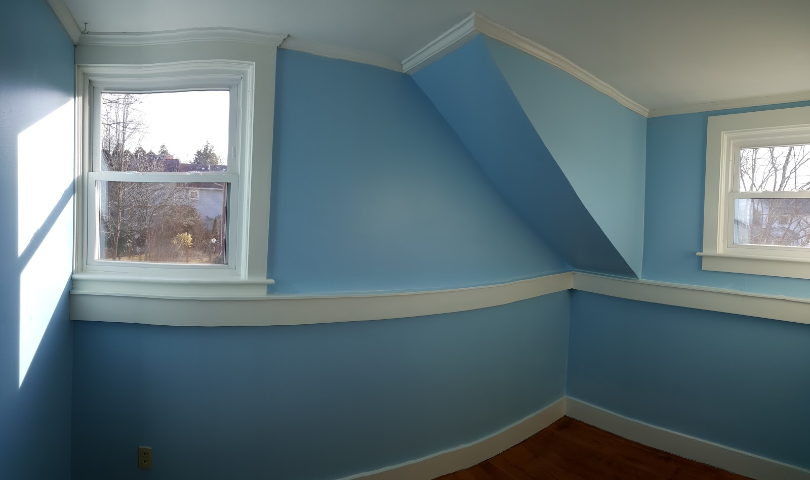
After a year or more of getting settled in a new place, a new place for a workshop has been established and a shelf layout started.  Step one, let's make the room sky blue and start day dreaming.

From there I made a few sketches for a possible model railway.


The thought here was that I could have fun with an inglenook and make just enough scenery to finish in the time we'll be living in this house.  Since I tend to favor structures and rolling stock, the layout is decidedly urban.  I'm keeping the Virgin and Lost Shore name, as well as the slogan, "the lost shore lines".

The bench work cantilevers off the wall and is attached with french cleats and T-nuts.  This will make removal a snap when we next re-locate and allow me to take the work with me.

Thursday, March 13, 2014

Dick Kerr WDLR 07

Everyone is probably getting bored of the Dick Kerr right now, but it's moving along.  Work has kept me away this week, but I still managed to finish up the cab.  I'm so happy with it that I'm going to take another crack at the sides--I think I can do better.  The test print of the cab is in the printer now.


One thing of note is that I "relieved" the windows in the cab, meaning I tapered the section of the wall near the window so they look near scale thickness.  This allows a thicker body wall. I'm going to give that treatment to the body sides.  You can see the tapering around the windows and the holes in the transparent version below.  I'm waiting to see the test print before I decide how to break it apart.


The other major step forward was developing a WDLR coupler.  I've designed it to work in a Kadee draft gear box.  I'm making a custom Kadee style box for the Kerr.  This way I can use standard Kadee centering springs, and allows for Kadee/WDLR couplers to be interchangeable.


My WDLR coupler head is faithful, save for an additional vertical hole I've added to allow for coupling with a small staple.  It's based on drawings and photos.  Here is the first test print.


Note the heel of the coupler is extended in this version--I had momentarily thought of an alternate centering scenario for use on a WDLR bogie, but quickly realized that the Kadee spring solution was a good one.

Monday, February 24, 2014

Dick Kerr WDLR 06

I've pulled the latest round of prints from the 3d printer, and am really pleased with the results.  I might adjust the assembly but I'm really pleased with the detail.  I'm going to add some relief to a couple edges to make things look thinner, and break the insulators away from the radiator.  The last revisions went really well.


Although I'm excited to work on the cab, I realized that I needed to sort the mechanism.  Returning to my previous work, I started by drawing the gearbox, wheels, and motor in both 2d and 3d.  I dropped the motor and gearbox in the model, and experimented with it's position.  I may abandon the flywheel, as it stands it looks like I can get everything into the hood.  Very cool.


One thing that's been bothering me about my previous work was that I only powered one axle.  Although this might work, with such a small loco and such a small motor I wanted more power transmitted to the rail.  This means connecting things with gears.  There's just enough room in the body cavity to offset the motor to one side and connect the two axles with a series of gears.  I started by drawing the Northwest Short Line spur gear because I thought that I might create a system that was integrated with the NWSL gearbox. . . then better sense prevailed.  A big part of the value of the NWSL gearbox is that the worm and associated thrusts are well worked out: messing with this seemed to invite gremlins.  I can always play with an integrated system later.  


The NWSL gears are all metric, the particular gearbox I chose is .03 MOD.  It seemed logical enough to continue with that gear specification.  I should point out that my version of the NWSL gear is close, but I may not be spot on, because I don't know exactly what the pitch of the NWSL gear is.  I made some good assumptions and may have it, but won't know until I test.  Given that my gears will not interact with the NWSL gears it does not matter, however I'd like to know. . . . 


I've been using Gearotic Motion and AutoCad for my mechanism design.  Gearotic will give you the proper axle spacing between two spur gears.  Using that information, it's possible to layout the precise geometry in AutoCad.  As my plan is to cast the chassis in lead shot filled resin, I'm simply including a minor shrinkage factor in the tolerance.


Gearotic allows you to work from the gear specification and the number of teeth to create a .dxf, stl, or gcode.  Although you can make a printable file from Gearotic, I'll probably use Rhino to design molds.  From there I can make rubber molds and cast gears in engineering resin.  Gearotic Motion was developed by Art Fenerty, who also developed Mach3, a corner stone of the Home CNC comunity.  I love the program.


Sunday, February 23, 2014

Dick Kerr WDLR 05

I traced this page through a stray photo.  It's been extremely helpful to see the radiator more clearly, and to gain some insight on the David Smith Drawings.  Also a clear idea of the hood radiator relationship.  Also note this Dick Kerr does not seem to have the trademark spokes in the front wheel set.  They must have been changed out at some point.  Similarly curious about the exhaust--assuming that's also been revised.

From: http://railsvagabonds.canalblog.com/archives/2012/09/13/25098989.html
No sooner did I find this than Bruce Wilson turned me on to this page.  That's where this fantastic high angle photo resides:

From: http://www.tacot-des-lacs.com/
Seeing this caused me to reconsider how I was joining the hood to the body, and whether I wanted to model the rail along the hood as part of my casting.  It seems to me that I should lower the joint to fit this image better.  Bruce also found this image (attribution in caption):

http://www.16mm.org.uk/newsite/Christmas_Quiz/2012images/Loco10.jpg
This of course clarifies some of the assumptions I have made.  Radiator needs to be deeper, and the insulator bases are indeed massive castings.  The image below illustrates how I've adjusted the rivets on top of the hood to better fit the images here.  While I can't measure them directly, I can adjust the number and spacing.  I now better understand the position of the straps on the roof--those are steel joints that don't necessarily align with the internal framework which is more closely aligned with the doors.  The framework is reflected in the additional lines of rivets.  I've also simplified thicknesses, and accepted 1.5mm as the necessary structural thickness at the sides (where they are not visible).  I've also increased the seam carve away to .4mm.


After tackling the hood, I returned to thickening and revising the insulator and radiator based on the photos.  The text on the radiator was bigger than I thought based on the David Smith drawings, and I chose to exaggerate it a bit more, hoping to make it legible in 7mm scale (1:43.5).  I also removed the "rails", figuring those could be added later with brass if I chose to do so.  I imagine a lot of these items (radiator cover, details) were removed by soldiers.  While it's possible that these parts were not removed until the units were resold as surplus after the war, soldiers are notoriously practical, and hate to waste time.


Here's the revised hood and radiator assembly.  It's off to the printer now.  I am looking forward to spending time on the cab tonight, after some time away from the computer. Getting exciting--I'm hearing the engine in my imagination. . . . .