Sunday, April 6, 2014

Mack AC 01

I took a break from digital work to finish up a couple Mack AC kits that have been sitting on my desk.  Mostly airbrush work, though I took some time to detail the dump as a coal delivery.  Bernie Kempinski pointed out that these could appear in a WWI layout. . . . I may have to get another.  The kit by Backwoods Miniatures is excellent, clean crisp castings with beautiful detail.  A couple fiddly bits one needs to be careful with, but overall very robust: highly recommend the kits.


The coal truck features tarps that were made from tea bags.  I lightly airbrushed them with white, beige, and black, and then formed them using dilute white glue.  I'm thinking I'll need to make a terrain base for photographs, as the real terrain is vastly out of scale!


The green truck is just a chassis for the moment.  I am going to build a sheep camp to put on it at some future point I think.  I took some time to look at the prototype Mack paint jobs, and it seemed that all red and all orange schemes were common, as was a green on red scheme.  In most cases the running gear was in color. Given that these are likely for the Lost Shore layout, I faded them a bit, as if they had been in the desert sun.

Thursday, March 13, 2014

Dick Kerr WDLR 07

Everyone is probably getting bored of the Dick Kerr right now, but it's moving along.  Work has kept me away this week, but I still managed to finish up the cab.  I'm so happy with it that I'm going to take another crack at the sides--I think I can do better.  The test print of the cab is in the printer now.


One thing of note is that I "relieved" the windows in the cab, meaning I tapered the section of the wall near the window so they look near scale thickness.  This allows a thicker body wall. I'm going to give that treatment to the body sides.  You can see the tapering around the windows and the holes in the transparent version below.  I'm waiting to see the test print before I decide how to break it apart.


The other major step forward was developing a WDLR coupler.  I've designed it to work in a Kadee draft gear box.  I'm making a custom Kadee style box for the Kerr.  This way I can use standard Kadee centering springs, and allows for Kadee/WDLR couplers to be interchangeable.


My WDLR coupler head is faithful, save for an additional vertical hole I've added to allow for coupling with a small staple.  It's based on drawings and photos.  Here is the first test print.


Note the heel of the coupler is extended in this version--I had momentarily thought of an alternate centering scenario for use on a WDLR bogie, but quickly realized that the Kadee spring solution was a good one.

Tuesday, February 25, 2014

Water Tower 06


I needed a break from the Kerr, so I've squeezed in some time on the water tower.  I feel like both the Kerr and the water tower are in striking distance for completion, and that I want to get them done while I've got some momentum going.


It was a real joy to lay the shingles on the tank lid--miracle of miracles, geometry works.  My rings of shingles, each customized to match the pitch of the roof and account for the taper fit as they were designed.  I'm not sure what I thought would happen, but am always suprised when something goes to plan! The sheet above is one of three shingle sheets--if you click on the water tower label at the right, you'll get the whole history of this . . . . 


Between laying shingles, I took a break to draw a finial, and I also started work on the band clamps. . . . while I did not intend to use the 3d printer on this, I thought that the roof was looking so good a real cap was in order.  It's stuck in the printer until tomorrow morning, as I printed it along side a larger part--I can look through the acrylic cover and see it dangling perfectly from the build platform. . . . .


Monday, February 24, 2014

Dick Kerr WDLR 06

I've pulled the latest round of prints from the 3d printer, and am really pleased with the results.  I might adjust the assembly but I'm really pleased with the detail.  I'm going to add some relief to a couple edges to make things look thinner, and break the insulators away from the radiator.  The last revisions went really well.


Although I'm excited to work on the cab, I realized that I needed to sort the mechanism.  Returning to my previous work, I started by drawing the gearbox, wheels, and motor in both 2d and 3d.  I dropped the motor and gearbox in the model, and experimented with it's position.  I may abandon the flywheel, as it stands it looks like I can get everything into the hood.  Very cool.


One thing that's been bothering me about my previous work was that I only powered one axle.  Although this might work, with such a small loco and such a small motor I wanted more power transmitted to the rail.  This means connecting things with gears.  There's just enough room in the body cavity to offset the motor to one side and connect the two axles with a series of gears.  I started by drawing the Northwest Short Line spur gear because I thought that I might create a system that was integrated with the NWSL gearbox. . . then better sense prevailed.  A big part of the value of the NWSL gearbox is that the worm and associated thrusts are well worked out: messing with this seemed to invite gremlins.  I can always play with an integrated system later.  


The NWSL gears are all metric, the particular gearbox I chose is .03 MOD.  It seemed logical enough to continue with that gear specification.  I should point out that my version of the NWSL gear is close, but I may not be spot on, because I don't know exactly what the pitch of the NWSL gear is.  I made some good assumptions and may have it, but won't know until I test.  Given that my gears will not interact with the NWSL gears it does not matter, however I'd like to know. . . . 


I've been using Gearotic Motion and AutoCad for my mechanism design.  Gearotic will give you the proper axle spacing between two spur gears.  Using that information, it's possible to layout the precise geometry in AutoCad.  As my plan is to cast the chassis in lead shot filled resin, I'm simply including a minor shrinkage factor in the tolerance.


Gearotic allows you to work from the gear specification and the number of teeth to create a .dxf, stl, or gcode.  Although you can make a printable file from Gearotic, I'll probably use Rhino to design molds.  From there I can make rubber molds and cast gears in engineering resin.  Gearotic Motion was developed by Art Fenerty, who also developed Mach3, a corner stone of the Home CNC comunity.  I love the program.


Sunday, February 23, 2014

Dick Kerr WDLR 05

I traced this page through a stray photo.  It's been extremely helpful to see the radiator more clearly, and to gain some insight on the David Smith Drawings.  Also a clear idea of the hood radiator relationship.  Also note this Dick Kerr does not seem to have the trademark spokes in the front wheel set.  They must have been changed out at some point.  Similarly curious about the exhaust--assuming that's also been revised.

From: http://railsvagabonds.canalblog.com/archives/2012/09/13/25098989.html
No sooner did I find this than Bruce Wilson turned me on to this page.  That's where this fantastic high angle photo resides:

From: http://www.tacot-des-lacs.com/
Seeing this caused me to reconsider how I was joining the hood to the body, and whether I wanted to model the rail along the hood as part of my casting.  It seems to me that I should lower the joint to fit this image better.  Bruce also found this image (attribution in caption):

http://www.16mm.org.uk/newsite/Christmas_Quiz/2012images/Loco10.jpg
This of course clarifies some of the assumptions I have made.  Radiator needs to be deeper, and the insulator bases are indeed massive castings.  The image below illustrates how I've adjusted the rivets on top of the hood to better fit the images here.  While I can't measure them directly, I can adjust the number and spacing.  I now better understand the position of the straps on the roof--those are steel joints that don't necessarily align with the internal framework which is more closely aligned with the doors.  The framework is reflected in the additional lines of rivets.  I've also simplified thicknesses, and accepted 1.5mm as the necessary structural thickness at the sides (where they are not visible).  I've also increased the seam carve away to .4mm.


After tackling the hood, I returned to thickening and revising the insulator and radiator based on the photos.  The text on the radiator was bigger than I thought based on the David Smith drawings, and I chose to exaggerate it a bit more, hoping to make it legible in 7mm scale (1:43.5).  I also removed the "rails", figuring those could be added later with brass if I chose to do so.  I imagine a lot of these items (radiator cover, details) were removed by soldiers.  While it's possible that these parts were not removed until the units were resold as surplus after the war, soldiers are notoriously practical, and hate to waste time.


Here's the revised hood and radiator assembly.  It's off to the printer now.  I am looking forward to spending time on the cab tonight, after some time away from the computer. Getting exciting--I'm hearing the engine in my imagination. . . . .


Saturday, February 22, 2014

Peter's Most Wanted 02: Steam Elephant 1815-1825

Next on the most wanted list is the Steam Elephant.  A replica derived from paintings, sketches, and extensive research resides at the Pockerley Waggonway, part of the Beamish Museum near Newcastle. 

Image from Wikipedia, author unkown.
Attributed to John Buddle and William Chapmen, the elephant is similar to Puffing Billy in that it has vertically oriented cylinders mounted in the top of the boiler with aerial motion rods.  That and the proportions of the smoke stack with a feed water heater at the base make it a very attractive subject in my eye. 

We're planning a trip to England to visit my wife's family, and I'm hoping we can make a trip to Beamish so I can see and survey the locomotive.  With that said, I'd be interested in hearing from anyone who is a step ahead of me, or has primary research on this locomotive or associated coal wagons. 

Image from Wikipedia

Wednesday, February 19, 2014

Peter's Most Wanted 01: 1850's B&O Iron Coal Car

I'm looking for information on a few subjects, and from time to time I will post them here.  If you've got solid information or research on the subject, I'd love to talk with you, as I'm interested in modelling these things.  A couple people who have helped on the Dick Kerr project will be receiving castings of the parts I make so they can complete their own models. . . . .and, I may in time release a limited kit of the Dick Kerr.

* * * Update * * *
I've checked in with the B&O Railroad Museum and have booked a ticket for may to photograph the car.  There are a few limitations associated with the museum, such as using a fabric tape measure and not climbing on or under the equipment, however none of it will prevent me from gathering what I need.  With luck I'll make progress on my other projects between now and then and be able to start a new thread for this one with original information this summer.

* * * Update * * *
In the span of a day I figured out that these are more commonly referred to as "Pot Hoppers"  That little piece of information lead me to an edition of B&O Modeler, and the fact that there is one of these cars in the B&O railroad museum.  I''d love to hear from anyone in the area with access to car 23001.
* * * * * *

First on the list?  B&O Iron Coal Car. . . .1850s.  I'm sure there is archival information somewhere, but I'm not there. . . . .anyone got the skinny on these pups?  The below page is from my copy of Civil War Railroads and Models  by Edwin P. Alexander.


I'm interested in the cars for their unique outline, and because they offer the opportunity to test some new digital modelling techniques combined with rapid prototyping.  (I'm interested in capturing the dents and dings).  It's also interesting to see the variation in the drawing above and the photograph which indicates construction was simplified in practice.  There a few images floating around the net, one is from the above book, and I can't find attribution for the other. . . . so forgive that it is not cited here...if someone has attribution please let me know so I can credit the source.


If you've read this blog, you know a couple things: 1) I've got a lot of irons in the fire, and 2) I tend to take a little time to finish things. . so patience will be in order. . .that said, some of my projects are heating up and really rolling again.  So, know that this all is on a longer time horizon.

Dick Kerr WDLR 04, Form 1 02

The Dick Kerr project is really moving along.  I've been printing prototypes on the Form 1 and modelling.  In the future I expect things to go faster, however I've been experimenting and learning.

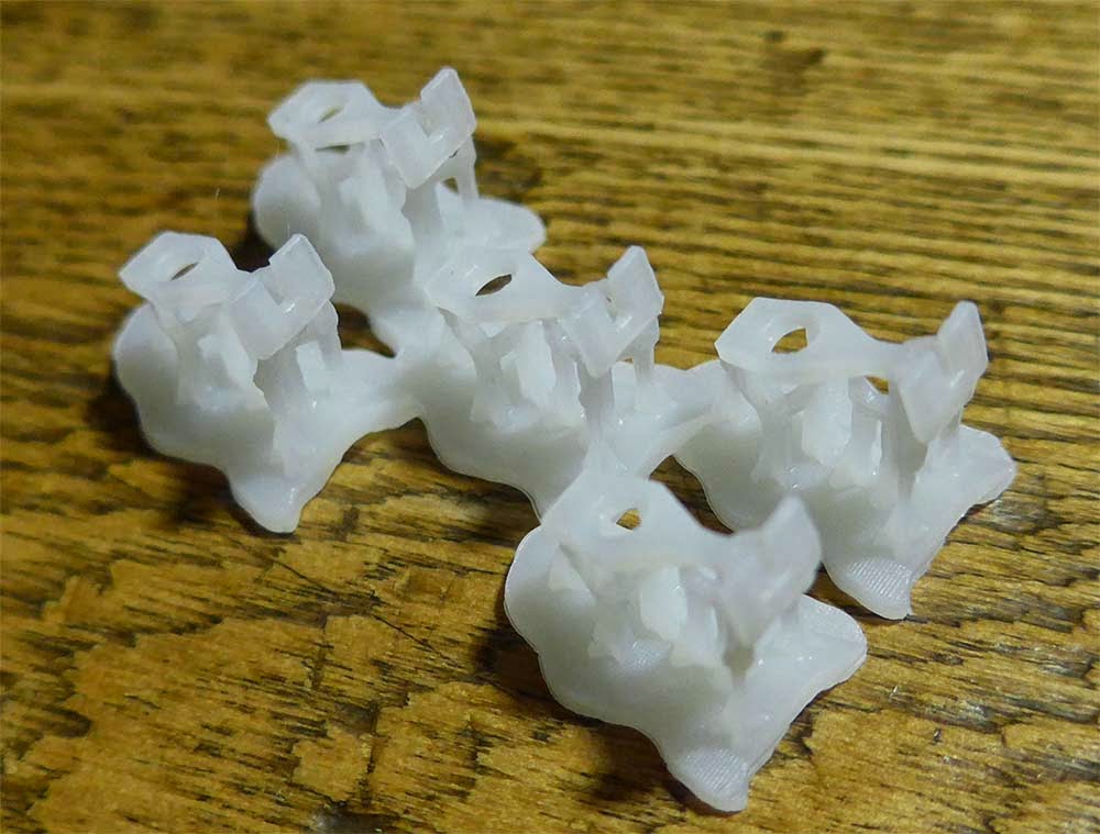
One of the peculiarities of designing things digitally you can draw detail at scale.  Even if you can print it, which the Form 1 can, you can't always see it.  I've spent several hours "beefing up" hardware so it's more visible in the final print.  It looks silly in the 3d model, but boy does it look good output at scale.  The images below illustrate, the lavender color is the exaggerated hardware, the orange is drawn near scale, with some thickness boost to meet minimum resolution requirements.


I've spent a good amount of time in both Rhino and Photoshop, extrapolating, doing and re-doing.  I started with the most delicate parts, and have gradually worked towards the more general ones--all the while re-building parts as needed based on lessons learned from successful and failed prints.


 My build style is to have a mother model based on an AutoCad drawing.  I keep things in logical subassemblies on layers.  I then "move them off" and regroup them as needed to export my .stl files.  This method preserves sanity and maximum flexibility.  I keep the coordinate locations the same between the two softwares, so if I need to work in line I can draw in AutoCad, which is much faster, and then import and know things will line up.  Precision counts.  If in doubt, rebuild it, it's faster than fussing with a repair.


As I make prints I'm updating the model.  Ultimately I'll make the cab to final standard--and skip doing the rivets in true scale, as it's pretty pointless.  


I'm also fairly certain that my ultimate plan will be to cast most of the model in resin, reducing the number of 3d printed parts in the final model.  That way I'll only have to print masters.  As I want a few, and I know Bruce Wilson wants a couple, casting will be more cost effective . . . .especially if I decide to make a few more.  

I have other exciting news on the mechanism design, but I'll save that for when I have some photos.

Sunday, February 2, 2014

Form 1 01


I've been off line for a while.  This fall I took a job in St. Louis. . . . which is great, except for the fact that I have a life and a business in Utah.  So, I'm commuting a 3000 mile round trip most weeks.  That's put a big dent in the model railroading.  It fits the title of being Random. . . . .

My Formlabs Form 1 printer arrived a couple weeks ago, and I've been putting it through it's paces, getting used to the ins and outs of stereo lithography.  For those not familiar with the Form 1, it uses a laser diode to cure resin in a vat.  This differs from the printers like Makerbot, where liquid plastic is deposited from a nozzle.  This laser cured resin allows finer resolution, and finer freestanding details.

Still wet pieces that have just come out of the resin vat, still adhered to the build platform.
The key to good results with the Form 1, in my observation so far boils down to three things:1) hygene, 2) grooming your resin, and 3) part orientation:

1) Anything involving optics and sticky goo in a tub over those objects in a world full of dust demands attention.  I keep a plastic bag over my Form 1, both to keep dust out, and to reduce further exposure to UV light in my daylit workshop (the orange cover is a UV filter).

Combs and confidence, and a sensitive touch, essential equipment.
2) It takes a few goes to get used to running your scraper over the optical silicone vat bottom, but you get the hang of it.  You want to search for floaters, and also gently dislodge any resin stuck to the bottom.  If you use inadequate support, your piece will stay on the vat, and not rise with the build platform.  The array of combs in the above photo is for getting out the loose bits once they are dislodged.  Formlabs has a couple good articles about this on their site.  Grooming resin is one of the most delicate things to do, because you risk dripping resin.  I've got the entire set up on a level piece of glass for ease of cleaning.

Although I labled this a support failure, both pieces with the "V" oriented that direction were distorted, so it was more than the supports.  Pieces facing the other direction were fine.  The hollow honey comb is something the Form 1 is very good at.  This bolster courtesy of Jim Lincoln.
3) Part orientation and support is key.  Depending on the form of the part it can disport as it undergoes the peel process.  Adding more supports will reduce distortion, but increases post processing.  After enough observation I'm getting a sense of the best combination of support and orientation.

Text on WSLCO washers, models courtesy of Jason Reis.

Unbelievably small and detailed journals for my Dick Kerr project.

Another shot of Jason's washers.
I've read a lot of reporting on the Form 1.  It's a fantastic machine, though it requires practice and a bit of patience.  Compared to my Subtractive Rapid Prototype machine it's really easy to use and far neater.  It's just slightly more involved than a laser cutter. More than worth it for it's unique capability.